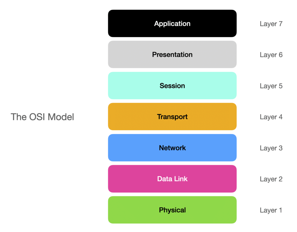
The OSI model, where OSI stands for Open Systems Interconnection, is a reference model that characteristics and standardizes the communication functions of a telecommunication system.
There are 7 Layers to the OSI Model:
- Application (Layer 7)
- Presentation (Layer 6)
- Session (Layer 5)
- Transport (Layer 4)
- Network (Layer 3)
- Data Link (Layer 2)
- Physical (Layer 1)

The Basics
It’s important to understand a few key concepts before we begin. I will briefly explain layers 4 through 7 so you have a basic understanding of their part in the OSI Model. Then we will dive into the more important layers to the network team (layers 1 through 3).
Application Layer (7) – This is the layer that is used by the end-software such as browsers or email clients. It provides the ability to send and receive information that is relevant to the user such as HTTP, FTP, SMTP/POP & DNS
Presentation Layer (6) – This layer is what prepares the data for the application layer. Specifically around encoding, encryption and compressing the data so the application receives it correctly.
Session Layer (5) – This is the layer responsible for the communication channels between two devices. It opens the session and makes sure that it remains open while the data is being transmitted. It also has checkpoints so if a session prematurely closes, it can pick up where it left off.
Transport Layer (4) – This layer is what controls data transfer between end systems and hosts.. This includes the data rates, how much to send and where it ends up. If you see TCP or UCP this layer is where those come into play. The transport layer is often grouped as the middle layer with layer 3 as that one is responsible for routing.
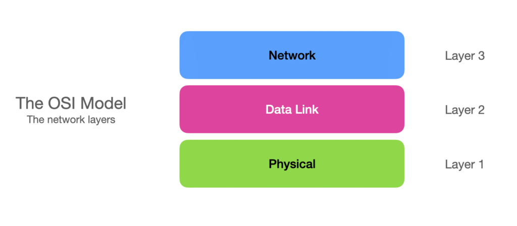
Layers 1, 2 and 3 (The Network Layers)
As mentioned, we typically deal mostly with layer 2 and 3 in the networking world and a bit of layer 1 depending on your responsibilities. Layer 2 and 3 are what handles how data is transmitted between devices and layer 1 is the physical layer of networking.

The network layers of the OSI model include physical (L1), data link (L2) and network (L3).
The Network Layer (layer 3)
The network layer handles the end to end routing of packets from one point to another. Layer 3 devices such as a router have routing tables which are used to forward data packets across networks. The network layer is also responsible for addressing devices on a network.This is where we find the Internet Protocol in its version 4 and 6, for instance.
Let’s see how routing decisions are made by routers. When a packet is received by a router, it will check the packet’s header for the destination address. If the destination address is the router itself, the packet will be processed by the higher OSI layers. Otherwise, if the destination address is not self addressed, the router will check if it has a route available for that destination address. If it does, the router will forward the packet to another host or send it out to an interface as indicated in its routing table. However, if the router doesn’t have any destination in its routing table associated with that destination address, it will discard the packet and notify with an ICMP message the source host. In alternative, a router can have a default route, which will be used as default next hop should a specific route be missing.
The following text snippet shows an example of a routing table on a Cisco router, and how routing decisions are made at layer 3. Each route entry is indicated by a source code (how the route is learned), a destination address (subnet + netmask), and a next hop or interface where that destination subnet is reachable. The following table has four total routes and one default route. Can you recognize them?
router#show ip route
Codes: C - connected, S - static, R - RIP, M - mobile, B - BGP
       D - EIGRP, EX - EIGRP external, O - OSPF, IA - OSPF inter area
       N1 - OSPF NSSA external type 1, N2 - OSPF NSSA external type 2
       E1 - OSPF external type 1, E2 - OSPF external type 2
       i - IS-IS, su - IS-IS summary, L1 - IS-IS level-1, L2 - IS-IS level-2
       ia - IS-IS inter area, * - candidate default, U - per-user static route
       o - ODR, P - periodic downloaded static route

Gateway of last resort is 172.16.0.1 to network 0.0.0.0

     172.16.0.0/24 is subnetted, 1 subnets
C       172.16.0.0 is directly connected, FastEthernet0/0
     10.0.0.0/24 is subnetted, 3 subnets
C       10.0.10.0 is directly connected, FastEthernet0/1.10
C       10.0.1.0 is directly connected, FastEthernet1/0
C       10.0.20.0 is directly connected, FastEthernet0/1.20
S*   0.0.0.0/0 [1/0] via 172.16.0.1
router#
Data Link Layer (Layer 2)
The data link layer’s primary responsibility is local delivery of frames between devices on the same LAN. To communicate with each other, devices use MAC addresses, which are unique identifiers assigned to a network interface controller (NIC) for use as a network address in communications within a network segment (source WiKipedia). This layer is also responsible for error checking and resolving, ensures data flow and transmission of data.
Layer 2 devices are called switches, and use the Content Addressable Memory (CAM) table to decide to which port to send frames they receive. A CAM table contains a list of MAC addresses associated with the port (or VLAN) where the device with that specific MAC address can be found. The following text snippet shows the content of a CAM table on a Cisco switch.
switch#show mac-address-table
          Mac Address Table
-------------------------------------------
Vlan    Mac Address       Type        Ports
----    -----------       --------    -----
   1    0006.5315.7bcf    DYNAMIC     Fa0/1
   1    000c.8507.6100    DYNAMIC     Fa0/1
   1    000c.8507.6101    DYNAMIC     Fa0/13
   1    b827.eb65.b90e    DYNAMIC     Fa0/18
   1    b827.eb6b.6fa3    DYNAMIC     Fa0/1
  10    000c.8507.6501    DYNAMIC     Fa0/13
  10    b827.eb95.04e2    DYNAMIC     Fa0/14
  10    b827.ebc1.6625    DYNAMIC     Fa0/16
  20    000c.8507.6502    DYNAMIC     Fa0/13
  20    b827.eb44.da64    DYNAMIC     Fa0/15
  20    b827.eb9c.025a    DYNAMIC     Fa0/17
Total Mac Addresses for this criterion: 11
switch#
What happens when a host wants to send a file to a destination host that is on a different LAN? The sending host will recognize by inspecting its local routing table that the destination IP address is not in the same network where it resides, so it will send it to the default gateway. The IP packets containing the file are encapsulated into layer 2 frames whose destination address is the MAC of the gateway. At that point the host transmits the frames, which they will first hit the local switch, then get forwarded to the router which acts as a default gateway, then by more layer 3 devices until it reaches the final network, or LAN, where the destination host is located. Return traffic will follow a similar process and flow.
Physical Layer (Layer 1)
Layer 1 is where we deal with the physical aspects of the OSI model. Layer 1 defines the electrical and physical specifications for network devices. These include cable types such as copper and fiber, cables and connectors, network adapters, etc. But it is also important to note that this layer works with data transmission in binary (series of 0’s and 1’s) to communicate data across its channel.
So if you want to get into laying cable and handling physical cable infrastructure, you’re going to be primarily working with the layer 1 of the OSI model. But it’s good to understand the basics of layer 1 if you’re going to be a NOC operator or network engineer.
How is it applied today?
It’s good to understand the OSI model at least from a basic fundamental standpoint. A software developer may only work with the application layer. But if you’re planning to work with networks you’ll need extensive understanding of layers 1 through 4.
The OSI Model is mostly a theoretical model (we all use the TCP/IP stack after all) but still is very relevant today as a reference model. It allows you to help troubleshoot issues such as connectivity and implement bottom up troubleshooting techniques. If a user’s laptop is having issues connecting to a web page, is it an application/browser issue, maybe their router (layer 3) is the problem. Or the cable running from the modem to the router is no good (layer 1).
This is actually why network monitoring is so useful. Is it the issue of a layer 2 or 3 device in your network? Is it on the web application side? Is it an issue within layer 4? And what about people working from home? Oftentimes you do not have insight into their network or Wi-Fi connectivity. People will often blame your application such as a VPN or web application but an issue with their layer 3 device (router).
Conclusion
Where you’re in high school aspiring to get into networking or just a techie who wants to understand your basic home networking, the OSI model is an extremely important element to understand. But this is just a brief introductory blog post about it. I would strongly encourage you to look even deeper to get even more real world examples on the OSI model and how they apply, maybe in your situation.
Stay tuned because while I briefly covered the physical layer, in the next post of this series I will dive more into cabling, connectors and much much more!


